The credit for the design of the relays goes to John Gilbert from Australia. He made a box that has the same type of relays for his Starlight CCD camera already. When I asked him to design a way to use the STV autoguider, he had a plan on paper in a day or two.For a basic write up about the advantages of auto guiding from SBIG, click here
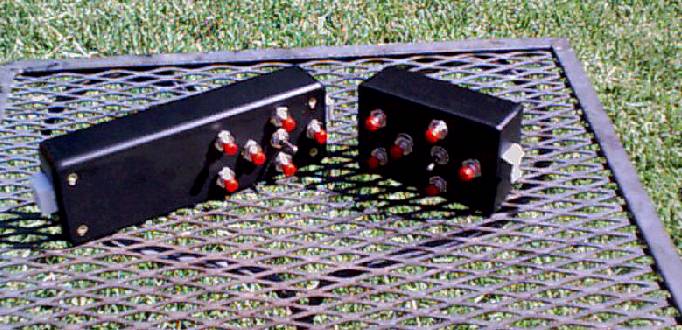
Here is what the finished product looks like now. The new version is on the left. Mel's standard handpad is on the right.

The way I did it, I cheated a bit, and used what Mel had already done. The whole button/switch assembly was removed from a handpad that Mel made and transferred to a longer box. A simple matter of drilling a few holes to match up what Mel had already done was all that was needed. The new parts fit into the new handpaddle where there are no buttons.
Here are the parts that I used:

The relays are from Radio Shack. Part number is 900-8073. These relays have a diode in them and is important to note.
The voltage is dropped to 5 volts from 12 sent out by the STV via a 7805 voltage regulator I had here. It is the same one Mel uses on the pcb.
The female cable connector is a 6 pin connector from Radio Shack as well. Any brand of 6 pin connector will do the job.The schematic that John sent me is below. It called for a new box and a DB-9 connector to go to another box. I wanted to keep this as compact as possible. Both ways will work however, just a matter of choice (and how willing you are to stuff all the wires and parts into a tiny box).

Drawings by John Gilbert
A single relay is pictured here:

Drawings by John Gilbert The SBIG manual details how to take the cover off the camera's computer box and change the way the relays work. This is needed to get the 12 volts supplied by the camera computer, stepped down to 5 via the 7805 voltage regulator, to the cable/relays. Please be sure to do this if you are going to do this job. The camera comes apart easily and there are no problems doing that (nothing falls apart or breaks).
Notes: When you change the jumpers inside the camera, the blue line is no longer unused. It now has 12 volts coming through it. The yellow wire is common for all the lines.
The wiring colors from the cable supplies by SBIG are different than those from Mel. Be sure to check these out to get the movement directions right.The relays I used are fastened to the underside of the cover of the plastic box. It does make things easier if you affix these first.
The numbering scheme for the relays is as follows:
There are 8 pins on the relay. On top of the relay there is a dot. That end, on the left side, looking from the top is the number one pin. (There is a dot on top between pins 2 and 14 from the diagram above). Be careful that you attach the wires to the correct pins.